×
- Hello
- Login or Register
- Quick Links
- Live Chat
- Track Order
- Parts Availability
- RMA
- Help Center
- Contact Us
- Shop for
- Subaru Parts
- Subaru Accessories
My Garage
My Account
Cart
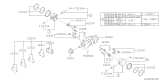
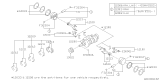
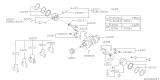
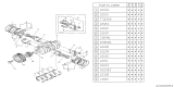
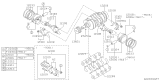
Genuine Subaru Legacy Crankshaft
Crank Shaft- Select Vehicle by Model
- Select Vehicle by VIN
Select Vehicle by Model
orMake
Model
Year
Select Vehicle by VIN
For the most accurate results, select vehicle by your VIN (Vehicle Identification Number).
24 Crankshafts found


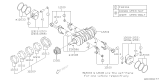
Subaru Legacy Crankshaft Complete
Part Number: 12200AA430$358.81 MSRP: $529.22You Save: $170.41 (33%)Ships in 1-2 Business Days

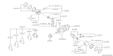
Subaru Legacy Crankshaft Complete
Part Number: 12200AA200$456.34 MSRP: $673.07You Save: $216.73 (33%)Ships in 1-3 Business Days
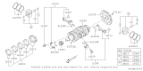
Subaru Legacy Crankshaft Complete
Part Number: 12200AA351$524.46 MSRP: $773.53You Save: $249.07 (33%)Ships in 1-3 Business Days
Subaru Legacy Crankshaft Complete
Part Number: 12200AA400$358.81 MSRP: $529.22You Save: $170.41 (33%)Ships in 1-3 Business Days
Subaru Legacy Crankshaft Complete
Part Number: 12200AA560$591.32 MSRP: $872.15You Save: $280.83 (33%)Ships in 1-3 Business Days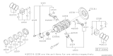
Subaru Legacy Crankshaft Complete
Part Number: 12200AA53A$592.82 MSRP: $874.37You Save: $281.55 (33%)Ships in 1-3 Business Days
Subaru Legacy Crankshaft Complete
Part Number: 12200AA180$446.04 MSRP: $657.88You Save: $211.84 (33%)


Subaru Legacy Crankshaft Complete
Part Number: 12200AA540$524.46 MSRP: $773.53You Save: $249.07 (33%)


Subaru Legacy Crankshaft Complete
Part Number: 12200AA350$524.46 MSRP: $773.53You Save: $249.07 (33%)

| Page 1 of 2 |Next >
1-20 of 24 Results
Subaru Legacy Crankshaft
Our website stands as the go-to online destination for OEM Subaru Legacy Crankshaft. With complete lines of genuine Subaru Legacy Crankshaft available at unbeatable market prices, we ensure top quality, reliability, and durability. Each part comes backed by the manufacturer's warranty, reinforcing your trust in our offerings.
Subaru Legacy Crankshaft Parts Questions & Experts Answers
- Q: What steps should be followed before installing the crankshaft to ensure proper main bearing oil clearance on Subaru Legacy?A:Before installation of the crankshaft, the main bearing oil clearance must be checked. Position the left crankcase section on a workbench with the bearing saddles facing up and wipe the main bearing surfaces with a clean lint-free cloth to keep them spotlessly clean. Clean the back sides of the main bearing inserts and lay one bearing half in each main bearing saddle in the crankcase, ensuring the tab on the bearing insert fits into the recess in the crankcase without hammering or damaging the bearing faces, and without using lubrication at this time. Clean the faces of the bearings in the crankcase and the crankshaft main bearing journals, then carefully lay the crankshaft in position in the left crankcase section. Trim three pieces of Plastigage slightly shorter than the width of the main bearings and place one piece on each crankshaft main bearing journal, parallel with the journal axis. Clean the faces of the bearings in the right crankcase and carefully lay it in position without disturbing the Plastigage. Install and tighten the crankcase bolts without rotating the crankshaft. Remove the bolts and carefully lift off the right crankcase section, ensuring the Plastigage remains undisturbed. Compare the width of the crushed Plastigage on each journal to the scale printed on the Plastigage container to obtain the main bearing oil clearances, which should typically fall between 0.0015 to 0.0023 inch (0.038 to 0.058 mm). If the clearance is not correct, double-check the size of the bearing inserts and recheck the crankshaft main bearing journal diameters, ensuring no dirt or oil was present between the bearing inserts and the main bearing caps or the block during measurement. Remove all traces of the Plastigage from the bearing faces or journals using a wood or plastic tool to prevent damage. Carefully lift the crankshaft out of the crankcase, clean the bearing faces, and apply a thin layer of engine assembly lube to each of the bearing faces in both crankcase halves, ensuring to coat the thrust bearing faces as well. Carefully lay the crankshaft in the left crankcase section, directing the connecting rods into the cylinder bores, and install the crankshaft/connecting rod assembly onto the bearings in the left crankcase before rejoining the two crankcase halves.

Related Subaru Legacy Parts
 Subaru Legacy Cam Gear
 Subaru Legacy Oil Pan
 Subaru Legacy Camshaft
 Subaru Legacy Oil Pump
 Subaru Legacy Crankshaft Pulley
 Subaru Legacy Piston Ring Set
 Subaru Legacy Oil Pan Gasket
 Subaru Legacy Rod Bearing
 Subaru Legacy Crankshaft Gear
Browse by Year
2025 Crankshaft 2024 Crankshaft 2023 Crankshaft 2022 Crankshaft 2021 Crankshaft 2020 Crankshaft 2019 Crankshaft 2018 Crankshaft 2017 Crankshaft 2016 Crankshaft 2015 Crankshaft 2014 Crankshaft 2013 Crankshaft 2012 Crankshaft 2011 Crankshaft 2010 Crankshaft 2009 Crankshaft 2008 Crankshaft 2007 Crankshaft 2006 Crankshaft 2005 Crankshaft 2004 Crankshaft 2003 Crankshaft 2002 Crankshaft 2001 Crankshaft 2000 Crankshaft 1999 Crankshaft 1998 Crankshaft 1997 Crankshaft 1996 Crankshaft 1995 Crankshaft 1994 Crankshaft 1993 Crankshaft 1992 Crankshaft 1991 Crankshaft 1990 Crankshaft